Example DI Algorithm
This page will direct you through the creation and usage of algorithms to utilize OpenDSO.
Introduction
This example project will walk through the creation of a DI (Distributed intelligence) enabled algorithm to simulate a demand response to a solar-smoothing problem (a "Duck Curve"). In this project you will be using Python, NATS (Neural Autonomic Transport System), the openFMB (Open Field Message Bus) conventions and OpenDSO (Open Distributed System Operation) GMS (Genesis Management Systems) for managing the equipment. By the end of this walk through you should know how to:
- Set up communication using OpenFMB Conventions
- Create and use a NATS server
- Apply an algorithm to real world devices
In this example, python is used. But with the use of protobufs for our OpenFMB, most languages are supported.
Overview
Optional: Deploy to nodes
Create model for use with GMS
The main purpose of this example application is to use an existing environment and apply an algorithm to it. For this project controllable loads will be used, but these could be anything (e.g. Breakers, PV (Photovoltaic), Reclosers, etc.). A known one line representing IEEE13 will be used, as shown.
#
Currently, CIM (Common information Model) files can be imported to create models, but an existing model will be used for this example.
The model is chosen for its familiarity, this demo will focus on demonstrating how to interact with devices using a simply designed algorithm.
Next step is to determine what the project is going to do. This is the exciting part! What problem is going to be solved? This example uses the controllable loads to model a common DI problem of demand response, but there are many different problems that could be devised with this set up.
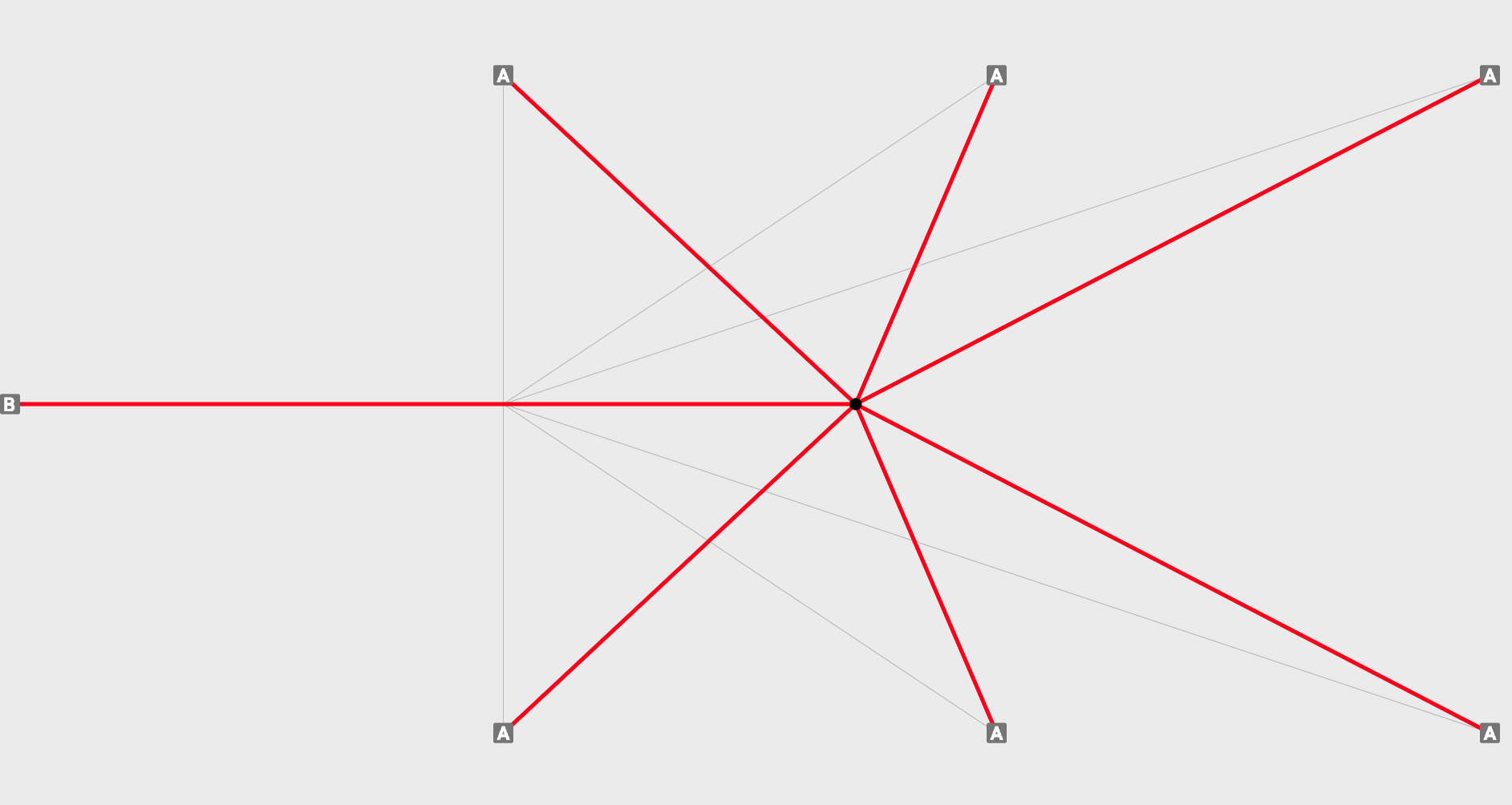
A straight-forward way to do this will require knowledge of the total load on the system at any given time and a way to compare it to a reference curve. Then the switch states can be used to keep the total load under the reference curve. The figure below shows an approach similar to the one used for this example. Instead of turning on and off devices, they will increase or decrease load depending on the threshold and their neighbors.
For this example a server (or your computer) is used to run the IEEE configuration in GMS. For simplicity sake we will also be starting the controllable loads locally, but these could be started on devices local to the load itself for a true distributed setup. The test will run each controllable load separately. It is set up this way to emulate a real world scenario where the devices aren't all in the same room.
Each controllable load is communicating via NATS (described below), using OpenFMB models to communicate. OpenFMB has profiles for different types of communication:
- Status
- Reading
- Event
- Control
In this example Status, Reading and Control profiles are used. Status profiles are used to read the state for the switch and look like:
{
  "readingMessageInfo": {
    "messageInfo": {
      "identifiedObject": {
        "mRID": {
          "value": "193dd689-e488-4296-b7ac-c3cd4386ad33"
        }
      },
      "messageTimeStamp": {
        "seconds": "1660065973",
        "nanoseconds": 875843321
      }
    }
  },
  "energyConsumer": {
    "conductingEquipment": {
      "namedObject": {
        "name": {
          "value": "L611"
        }
      },
      "mRID": "a06e75c5-9504-483f-a4b0-db2d816f8291"
    }
  },
  "loadReading": {
    "readingMMXU": {
      "PhV": {
        "phsA": {
          "cVal": {}
        },
        "phsB": {
          "cVal": {}
        },
        "phsC": {
          "cVal": {
            "mag": 3885.20849609375
          }
        }
      },
      "VA": {
        "net": {
          "cVal": {
            "mag": 1000000
          }
        },
        "phsA": {
          "cVal": {}
        },
        "phsB": {
          "cVal": {}
        },
        "phsC": {
          "cVal": {
            "mag": 1000000
          }
        }
      },
      "VAr": {
        "net": {
          "cVal": {
            "mag": 280000
          }
        },
        "phsA": {
          "cVal": {}
        },
        "phsB": {
          "cVal": {}
        },
        "phsC": {
          "cVal": {
            "mag": 280000
          }
        }
      },
      "W": {
        "net": {
          "cVal": {
            "mag": 960000
          }
        },
        "phsA": {
          "cVal": {}
        },
        "phsB": {
          "cVal": {}
        },
        "phsC": {
          "cVal": {
            "mag": 960000
          }
        }
      }
    }
  }
}
These can be viewed using the OpenFMB Inspector tool in the GMS once setup. Reading profiles are used to provide data about the device, in this case Voltage and Wattage data and look similar to:
{
  "statusMessageInfo": {
    "messageInfo": {
      "identifiedObject": {
        "mRID": {
          "value": "9fa88a8a-447a-41ce-8a80-d81907effe21"
        }
      },
      "messageTimeStamp": {
        "seconds": "1660065973",
        "nanoseconds": 874984251
      }
    }
  },
  "energyConsumer": {
    "conductingEquipment": {
      "namedObject": {
        "name": {
          "value": "L652"
        }
      },
      "mRID": "a0cb45a6-a964-4621-949c-805b23a191c8"
    }
  },
  "loadStatus": {
    "loadStatusZGLD": {
      "loadEventAndStatusZGLD": {
        "PointStatus": {
          "rampRates": {
            "positiveRealPowerKWPerMin": {
              "value": 1
            }
          },
          "state": {
            "value": "StateKind_on"
          }
        }
      }
    }
  }
}
Lastly, a LoadControl profile will be used to send control messages to the controllable loads to increase or decrease load. These messages look similar to:
{
  "controlMessageInfo": {
    "messageInfo": {
      "messageTimeStamp": {
        "seconds": "1659984702",
        "nanoseconds": 604905020
      }
    }
  },
  "energyConsumer": {
    "conductingEquipment": {
      "namedObject": {
        "description": {
          "value": "_solarReading.description.c_str()"
        },
        "name": {
          "value": "Pump"
        }
      },
      "mRID": "c8db06d5-94e5-4b88-a430-a0db4a2fee6e"
    }
  },
  "loadControl": {
    "loadControlFSCC": {
      "controlFSCC": {
        "controlScheduleFSCH": {
          "ValACSG": {
            "schPts": [
              {
                "scheduleParameter": [
                  {
                    "scheduleParameterType": "ScheduleParameterKind_VAr_net_mag"
                  },
                  {
                    "scheduleParameterType": "ScheduleParameterKind_W_net_mag",
                    "value": 0.13369999825954437
                  }
                ],
                "startTime": {
                  "seconds": "1659984702",
                  "nanoseconds": 604905020
                }
              }
            ]
          }
        }
      },
      "loadControlScheduleFSCH": {
        "ValDCSG": {
          "crvPts": [
            {
              "reactivePwrSetPointEnabled": {},
              "realPwrSetPointEnabled": {
                "ctlVal": true
              },
              "startTime": {
                "seconds": "1659984702",
                "nanoseconds": 604905020
              }
            }
          ]
        }
      }
    }
  }
}
Create Nats framework
The next thing that needs to be done is to establish the communication with the devices and GMS. This is done using NATS, which is a publish-subscribe model specifically designed for edge and distributed systems. More information can be found here: NATS.io
Currently there are at least two repositories that can be used for python: nats-python - nats-io
We use both in this example. Feel free to use the one that you prefer.
Due to the nature of the pub-sub set up, the design will need to be asynchronous, so that each message is handled as expected. To do this using python, Asyncio can be used.
To begin, a listener will need to be set up so that the messages from each of the controllable loads can be subscribed to. Since this algorithm will be running on each node, a way is needed to uniquely identify the individual nodes, and the controllable loads they will communicate with. mRID's will be used for this purpose, these can be generated uuid's.
Thus, the main will look something like this:
if __name__ == '__main__':

    #command line parsing
    parser = argparse.ArgumentParser()
    parser.add_argument("-m", "--mrid", help="node mrid file,  default=self/mrid1.json", required=False, default= "self/mrid1.json")
    parser.add_argument("-s", "--server", help="NATS server name, default=localhost", required=False, default = "localhost")
    args = parser.parse_args()
    mrid_path = args.mrid
    server = args.server

    #import self info
    f = open(mrid_path)
    jsonFile = json.load(f)
    mrid = jsonFile["mrid"]
    name = jsonFile["name"]
    desc = jsonFile["description"]
    if (len(mrid) != 36):
        sys.exit("Invalid MRID, exiting...")
    myEquipmentMrid = mrid

    #import group config
    f = open('config/node.json')
    config = json.load(f)
A few things to note here. The mRID is arbitrarily set for this node, as well as the others. These are set in a config file along with the priority of the device. The file is read and subsequently used to identify the neighbors as well as the priority level that tells which order they should shut down in. Similar to how we don't want to shut off the AC as the first load in the heat of summer, but a pool pump might be okay. This looks like this:
{
   "735bc471-9ad9-4843-b0ae-a83a8a6f8775" : 6,
   "d2658598-7562-49d5-a004-9adda8ff3f86" : 1
}
Where each device is represented. The above example is if only 2 devices were used. The first number is the mRID of a pi, the second is its priority level. The higher the level the later to shut off it will be.
A self file is used to identify the unit that is running and any configs associated. This could be created as part of the creation of a Kubernetes cluster and would not need to be here.
The other item that must be declared is the NATS server. This is something that will be handled by the GMS set up when it is started up. The IEEE model that will be used can be found here and should be started with
./start.sh -l
The address will be the ip of the server it is run on. Likely the computer you are working from now. The GMS can be accessed, once running at, https://localhost:8081/. You may need to enable https via local host: https://communicode.io/allow-https-localhost-chrome/
With the connection in place, the subscriptions to the other nodes on the network can be set up.
    # Create class item for each device we will be listening
    for mrid in config:
        equip = Equipment(server, mrid)
        equip.priority = config[mrid]
        equipmentByMrid[mrid] = equip

    for mrid, equip in equipmentByMrid.items():
        equipmentOrdered.append(equip)

    #Add name and description of local node to class
    equipmentByMrid[myMrid].name = name
    equipmentByMrid[myMrid].description = desc

    # Order equipment by priority level
    equipmentOrdered = sorted(equipmentOrdered, key=lambda x: x.priority)
As can be seen in the above section, the mRID and priority of each device is taken from the config file and added to a class. That class is then ordered by priority. Finally, three callbacks are set up.
- Get Reading
- Get State
- Get Threshold Value
So let's start by taking a look at the reading callback
async def readingCallBack(msg):
    global equipmentByMrid

    # openFMB reading
    mrid = msg.subject.split('.')[3]

    #Converts serialized message to Json
    Profile = Profiler.loadReadingProfile()
    Profile.ParseFromString(msg.data)
    clReadingJson = json.loads(MessageToJson(Profile))

    #Get values from NATS message
    wattage = 0
    voltage = 0
    var = 0
    if "mag" in clReadingJson["loadReading"]["readingMMXU"]["PhV"]["phsA"]["cVal"]:
        voltage = clReadingJson["loadReading"]["readingMMXU"]["PhV"]["phsA"]["cVal"]["mag"]

    if "mag" in clReadingJson["loadReading"]["readingMMXU"]["W"]["net"]["cVal"]:
        wattage = clReadingJson["loadReading"]["readingMMXU"]["W"]["net"]["cVal"]["mag"]

    if "mag" in clReadingJson["loadReading"]["readingMMXU"]["VAr"]["net"]["cVal"]:
        var = clReadingJson["loadReading"]["readingMMXU"]["VAr"]["net"]["cVal"]["mag"]

    #Set class variable values based on reads
    if mrid in equipmentByMrid:
        equipmentByMrid[mrid].voltage = voltage
        equipmentByMrid[mrid].wattage = wattage
        equipmentByMrid[mrid].var = var
        if equipmentByMrid[mrid].wattage > equipmentByMrid[mrid].highestWattage:
            equipmentByMrid[mrid].highestWattage = equipmentByMrid[mrid].wattage
        await logicHandler()
    else:
        print("Warning: nats topic does not match any configured equipment.")
This callback takes the message that triggers the call back, pulls out the mrid, and then transforms the OpenFMB into a human readable form. From there it extracts the voltage, and wattage adding it to the class variable. Lastly it calls the logic handler, this call is repeated in each call back.
The last callback is the threshold call back, since it is sent in plain text, it can just be saved to a variable directly.
Each of these messages is being published over NATS on a subject unique to the device:
openfmb.loadmodule.LoadControlProfile.[mrid]
This set up allows subscription to things at a granular level, while enabling scope expansion if needed.
openfmb.loadmodule.*
This subject would return all readings and statuses, as well as any other profiles that were set up for all controllable load modules publishing to this NATS server.
Write algorithm
If you remember, each of the call backs ended by calling a function called "logicHandler()"
This is where the logic will be applied. The logic should be checked with each reading, state change and threshold change of the system, so this makes sense.
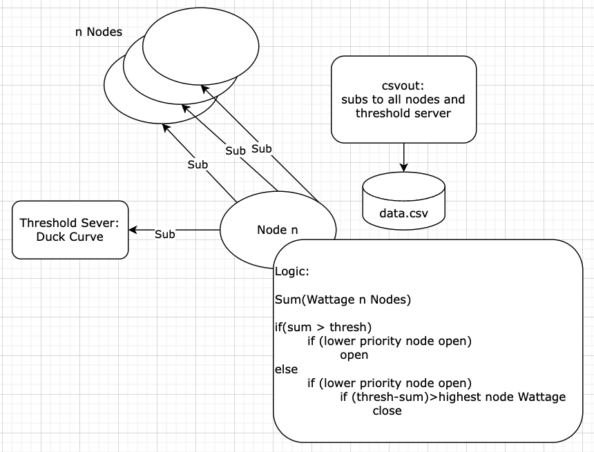
As a quick refresh, a node should be turned off if the sum wattage of the nodes is above the latest threshold value. The inverse is also true, a node should be turned on if the sum of the wattage is below the latest threshold value. There is some additional logic, based around priority and known device wattage, but for the sake of simplicity this is the reduced logic:
sum = 0
for n in equipmentOrdered:
    sum += n.wattage

if(sum > threshold):
    decrease load
else:
    increase load
This boils down to a relatively simple equation. The wattage of all nodes is summed, and then via a compare an action is completed. The logic can be built out to whatever makes sense past this.
The next question becomes the interaction with the real life devices.
This is done using NATS and OpenFMB! Choose the correct protobuf for the language that is being used. With that library linked, a message that will tell the device to turn off as expected can then be published. This same protobuf is used in the communication needed to sub to the devices.
The nats interaction is a little different in this code, that is because another library is being used for trial purposes. Each seems to work well, so feel free to select the preferred library and work from it.
    def setValue(self, p, q):
        self.nc.connect()
        statusProfileUpdate = LoadModule.LoadControlProfile()

        messageinfo = statusProfileUpdate.controlMessageInfo.messageInfo
        messageinfo.messageTimeStamp.seconds = round(time.time())

        io = statusProfileUpdate.energyConsumer.conductingEquipment
        io.mRID = str(self.mrid)
        io.namedObject.name.value = self.name
        io.namedObject.description.value = self.description

        schPt = CommonModule.SchedulePoint()
        sp = CommonModule.ENG_ScheduleParameter()
        sp.scheduleParameterType = 35
        sp.value = p
        schPt.scheduleParameter.append(sp)
        sp.scheduleParameterType = 40
        sp.value = q
        schPt.scheduleParameter.append(sp)
        schPt.startTime.seconds = round(time.time())
        statusProfileUpdate.loadControl.loadControlFSCC.controlFSCC.controlScheduleFSCH.ValACSG.schPts.append(schPt)

        setEnable = statusProfileUpdate.loadControl.loadControlFSCC.loadControlScheduleFSCH.ValDCSG.crvPts
        rp = LoadModule.LoadPoint()
        rp.realPwrSetPointEnabled.ctlVal = (p != 0)
        rp.reactivePwrSetPointEnabled.ctlVal = (q != 0)
        rp.startTime.seconds = round(time.time())
        setEnable.append(rp)

        self.nc.publish(self.getPublishStatus(), payload=statusProfileUpdate.SerializeToString())
        self.nc.close()
You can see in the code above that the message is constructed based on the protobuf that was grabbed earlier. The subject needs to be set up as noted before ending with the mRID of the publishing device. Then set the value of the controllable load to the value that was passed. Other information such as the time stamp, can also be included. The message that has been created can then be published to the NATS server.
Deploy to nodes
Once you have the code working as expected on a local device, you can containerize it using docker to ensure that the correct packages are available on whatever device you put it on. Our DockerFile looked like this:
# 1. Base image
FROM --platform=linux/arm64/v8 python:3.8
#--platform=linux/arm64/v8

# 2. Copy files
COPY . .

# 3. Install Dependencies
RUN pip install --no-cache-dir -r requirements.txt

#startup
CMD ["python", "nodes.py"]
The platform we were building for was ARM based (raspberry pi), so --platform can be removed if you are not.
For our set up we created a Kubernetes cluster using raspberry pis that we could deploy too. This took a little time to set up but made the deployment much simpler. As we could push the same software to each node.
Trying it out
Download and start the IEEE13 GMS server
It should be started with
./start.sh -l
Open a browser to: https://localhost:8081/
Login
Install the python requirements
sudo apt install python3
sudo apt install pip3
RUN pip3 install --no-cache-dir -r requirements.txt
Start the threshold server
cd ~/nodes
python3 threshold_server.py -f config/thresholdData.txt
-h will provide options
Start the nodes.py for each controllable load in the environment
python3 nodes.py -m self/mrid1.json
You will want to run this 8 times, replacing mrid1 with mrid2, etc.
Voila! You will see the devices start to change in real time as they work together to stay under the threshold curve.
You can also use the included DockerFile to create docker container to run the project.
Python Script
This repo contains 3 different scripts:
nodes.py
Purpose: This is the core algorithm that determines the behavior of the BERT plugs
To Run: This algorithm is already set up on the PIs and will be started automatically when the devices are plugged in
Other notes: The priority of the devices is set via mrid in config/nodes.json
The openFMB messages are set up for receiving status, read and setting status.
These can be reused with different logic to read and control the devices over NATS using the openFMB protocol
threshold_server.py
Purpose: This is the value curve that the plugs are set to follow.
To Run: a config file is provided at nodes/config/thresholdData.txt, but any input can be used.
usage: threshold_server.py [-h] -f FILENAME [-m MAXVALUE] [-d DELAY] [-s SUBJECT] [-H HOSTNAME]
python3 threshold_server.py -f config/thresholdData.txt